Synopsis
SysML is an UML reconfiguration (subset, extensions, and profile) dedicated to systems modeling. The introduction of blocks as the basic unit of systems description can be seen as its pivotal change, in particular when block diagrams are used as substitutes for class ones.

But the generalized employ of block diagrams may raise a few questions: should its scope be limited ? what kind of systems are targeted ? what kind of models are to be built ? and what are the benefits for modeling processes ?
Scope: Actual Objects & UML blind spot
The description of instances has always been a well known weakness in UML. To be sure, object diagrams were part of UML initial specifications; yet, they have been jettisoned due to their lack of clear definition and purpose; finally they have been “overlooked” in UML last versions.
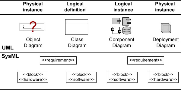
That neglect has left a blind spot in UML modeling apparatus: if components and deployment diagrams are available to deal with logical and physical instances at the end of the engineering process, UML 2.5 has nothing equivalent for the context “as-it-is” at development process inception.
So, SysML new focus on physical systems offers a worthwhile opportunity to make up for the disappointments of object diagrams, introducing the block diagram as the tool of choice for requirements specifications relative to existing systems and environment, along class diagrams for the definition of their logical counterpart, and components and deployment diagrams for logical and physical implementations.
Such a restricted focus on physical instances would meet the parsimony principle (aka Occam’s razor) and would provide for continuity with UML and clarity of semantics and purposes.
But that opportunity is to be missed if, instead of focusing on the blind spot of requirements with regard to actual configurations, block diagrams are used indiscriminately for instances and classes, blurring the critical distinction between physical and logical components, and introducing overlaps and semantic ambiguities across diagrams.
Target: Mechanical vs Logical Systems
Whereas SysML clearly suits the needs of mechanical and civil engineering, its preferred hierarchical approach may fall short when systems cannot be reduced to equipment built from hardware and software.
Nowadays, with software colonizing every nook and cranny of actual and virtual worlds (soon to be known as the Internet of Things), a broader systemic approach may be necessary, with systems modeled as collaborative frameworks between agents, devices, and computer systems.

Being by nature logical, distributed, heterogeneous, and in continuous mutation, these systems are not easily described by hierarchies of physical components. And even when blocks can be used to represent hardware and software, separately or jointly, block diagrams tend to privilege trees of physical components intertwined by logical or functional associations.
That bias in favor of physical architectures may put functional ones on the passenger seat; as a consequence, critical software alternatives may be shrouded, bypassed, or emerge at lower levels of composition; too late and too local for sound architectural decision-making.
Models: Requirements vs Design
The bias introduced by block diagrams may be of no consequence as far as SysML is used for requirements specifications. But that may not be the case if it is also used for design, especially if block diagrams are used all along without a transition being clearly marked between requirements and design.
At issue here is the qualitative and quantitative edge of software capabilities over hardware ones: a prejudice for block hierarchies could compromise the plasticity (ability to change architecture without affecting performances) and versatility (ability to perform different activities without changing the architecture) of systems designs.
Moreover, apart from being inherently more rigid than networks, block hierarchies are built along a single dimension combining logical and physical features. The overall plasticity of such hierarchies is to be constrained by the plasticity of their physical elements, and their versatility will be similarly limited by hardware constraints on software interfaces.
Finally, as the semantics of ports and flows used to define communication between blocks don’t force an explicit typed distinction between hardware and software, chances are for mixed designs to limit systems modularity. That points to the shortcomings of untyped modeling constructs.
Processes: Overheads of Untyped Constructs
Paradoxically for a supposedly specific profile, SysML’s blocks can be seen as untyped constructs to the extent that they apply to both physical and logical objects, as well as constraints.
Like their programming counterparts, non typed modeling constructs induce ambiguities which have to be clarified by comments or additional constructs. That is where SysML requirements diagrams come into view.
To begin with, requirements are meant to be the source of engineering processes before anything can be assumed with regard to their format or modeling constructs.
Given that premise, usually accepted by leading tools providers, they are to be expressed through text; the very notion of “requirements diagram”, which suggests some formalism, may sound like an oxymoron, and “requirements editor” would be less confusing.
Alternatively, e.g for scientific applications, if the assumption can be dropped requirements can be directly captured using formal expressions and constraints.
Whereas SysML supports both options, the use of untyped blocks may begets redundancy and confusion. Since block diagrams can be used for (physical) targets as well as for (logical) constraints, three policies can be considered:
- Text: requirements are documented with their own diagram and linked to physical blocks (a).
- Constraint: requirements are represented by logical blocks linked to physical ones (b).
- Text and constraint: requirements are documented with their own diagram and linked to constraints represented by logical blocks, themselves linked to physical blocks (c).

Embarrassment of riches may be especially challenging when the problem is to bring some order to unstructured and ambiguous inputs. In the case of requirements traceability, adding layers of dependencies may rapidly result in acute “spaghetti syndrome”.
Moreover, the apparent benign choice of diagrams may compound the risks on design mentioned above by masking the critical transition from requirements (documented as such or by constraints) to architectures (as described by physical blocs).
Conclusion
The proper use of block diagrams has to make up for being simultaneously too restrictive and too permissive.
With regard to structures (and consequently architectures) block diagrams strongly lean towards physical hierarchies; to quote: “blocks provide a general-purpose capability to model systems as trees of modular components.”
With regard to semantics blocks put no limit on what can be represented; to quote: “The specific kinds of components, the kinds of connections between them, and the way these elements combine to define the total system can all be selected according to the goals of a particular system model.”
Since, to quote: “SysML blocks can be used throughout all phases of system specification and design, and can be applied to many different kinds of systems”, no wonder block diagrams tend to put class diagrams and their sound and consistent semantics to the margins.
These pitfalls can be avoided by using SysML as a typical UML profile, in particular by limiting the use of block diagrams to the modeling of systems as-they-are, and using standard UML2 diagrams with SysML profile and stereotypes otherwise.
PS. SysML 1.4 appears to make amends by deprecating or clarifying some redundant or confusing elements with regard to UML.
Further Readings
- Hybrid Sport Utility Vehicle (SysML)
- What is to be represented
- Building Bridges
- A Modeling Paradigm
- The Finger & the Moon: Fiddling with Definitions
Hello Remy
Something I totally agree with is the fact that block diagram blurs at first sight the disctinctions between physical/logical/functional/operational “decomposition” in a hierarchical way because they can be applied to any of these kind of decomposition.
The block/parts/ports can be used to create functional decomposition, which can be allocated to logical decomposition, which can be then allocated to physical decomposition. Any other decomposition can be added according to your need. The allocations are very important, because they transform your tree-like decomposition, into a graph, which is more appropriate to model complex system. As the language does not constraint the method, the “how and why” you create separate block decomposition, and how you link them, is your business. IMHO, this increases the difficulty to deploy SysML as an efficient way of modelling.
People doing system models have answered to this issues by either quitting SysML to create their own DSL, or trying to add their profile to keep SysML as foundation, an enhance its capabilities in particular domains.
So, cleary, it is blurring the picture, but is not limited to one dimension.
And yes, the transitions between the stages of development must be well thought at method and tool level, prior to deploy SysML.
Best regards
I believe the first diagram in the article provides a straight answer: block diagram should be understood (and used) as an upgraded object diagram.
Sorry Remy, I added unnecessary e after m and before y. Best wishes
Remey:
Very profound but still somewhat abstract for simple direct application. I have no specific disagreement but I do not know to use these observations.
This set off the following thoughts.
1A: In the first place how did block diagrams emerge? IMO they are used to represent physical systems without showing the detailed properties of the “subsystems” or “elements” that make up the system. They have been and are useful to know & show the “gross and essential” components of systems. Since Block Diagrams emerged from concrete physical systems, they continue to be physical though the details are withdrawn. In general block diagrams are used without much rigor and precision.
1B: Around 70s, conceptual or logical block diagrams emerged without any physical implications: CONCEPT MAPS. I understand that UML Class Diagrams are more elaborate and sophisticated extensions of “concept maps”.
2: A related question arises. Can processes or phenomena which are special cases of systems, also be represented by block diagrams? Yes, but IMO they do not convey much and that is why processes are invariably represented as a set of processes (activities as elements) with specific inputs and outputs. Since processes are special anyway, there is no point in using more generalized representations of their components.
3: I find that class diagrams are great for modeling physical and logical configurations of “systems” but I am not in a position to view or understand how they are related to Block Diagrams. Since both of them represent systems, “there should be a way of transforming one into other by adding or withdrawing details”. If that can be done simply and easily, the models will represent things with sufficient precision to be useful for understanding or creation. Otherwise models will have limited validity and versatility and they have to be supplemented with case to case specific external explanations (which is to admit that we failed to model).
It is possible that your article has answers to the above. I have to study it again and or think more on these concepts and their relations.
PVN 20SEP15