See also: Business cases
Objectives
Use cases must meet two overlapping yet contrary goals, namely (1) specify functional requirements as expressed by business analysts, and (2) provide a clear, consistent, and non ambiguous basis to system analysts.

Whereas mutual understanding is certainly helpful, the risk is twofold:
- Business analysts may unknowingly introduce biases into system architecture.
- System analysts may reinterpret business needs to fit them into their modeling languages.
The objective of use case patterns is to bridge the gap between business and system models without altering requirements contents nor preempting architectural options. For that purpose, representation patterns are to map execution units associated with use cases into functional components along the functional architecture perspective.

Use Cases & Functional Architecture
As often noted, the fundamental conundrum with use cases is to describe system interactions with users without introducing architectural bias. One way to solve the problem is to tell apart the functional level, which duly belongs to use cases, and the technical one, which doesn’t. That can be done by introducing a level of indirection between business and technical concerns.

- Since access to persistency units potentially affects all business processes, it is the most constraining functionality, and therefore the first to be set apart. That is best illustrated by services implementing CRUD primitives .
- The architectural footprint of execution units is by nature more limited and is usually the backbone of use cases. Checking access rights and authorizations is a standard example.
- Accesses to systems must be set apart since they are executed locally, before calling on system shared resources. Moreover, since roles (actors in UML parlance) are defined by organizations, the corresponding interfaces should be defined independently of interactions which may have to process the details before carrying on with business rules. For instance, identification can be achieved by matching some input with a value object stored or generated locally, or even obtained through another service.
These stereotypes can then be used to map use cases to architectures functional capabilities.
Use Cases & Coupling Constraints
Given that the primary objective of use cases is to describe how systems interacts with their environment, the first step should be to characterize the coupling constraints.

Coupling constraints depend on the distribution of shared activities and objects:
- Local: use cases executed in one location, i.e, with exclusive control over resources and timing; e.g the recording of water levels (a).
- Synchronization of activities: use cases executed in more than one location, i.e using resources managed independently and/or run under different clocks; e.g coordinating (c) sluices management (a,b).
- Synchronization of objects: use cases updating entities across address spaces and time-frames; e.g water levels and sluices status must consistently recorded (d) if used to manage sluices (c).

Synchronization constraints are said to be weak when they can be managed at component level (control or entity), strong or real time (aka synchronous) when they preempt the execution of any other use case, i.e nothing is supposed to intervene during the interval.
Whereas synchronization constraints are rooted in business requirements, they are not necessarily expressed with regard to systems functional capabilities. Hence the benefits of organizing use cases accordingly.
Use Cases Basic Profiles
Use case <<include>> connectors can be used to align use cases footprint with functional architecture:

- Batch use cases: triggered independently of contexts; e.g compute expected levels.
- Transactional use cases: triggered by roles played by users through symbolic communication; e.g update targeted levels.
- Service use cases: triggered by roles played by systems through symbolic communication; e.g publish status and levels.
- Real time use cases: triggered by roles played by physical devices; e.g monitor actual status and levels.
These profiles can also be refined with binding constraints:
- The lest constrained use cases are functions executed instantly and independently of contexts and persistent representations.
- Batch use cases cannot be executed instantly yet don’t depend upon context events or agent expectations.
- Transactional use cases do depend on actors expectations and they also take time to complete.
- Service use cases do not take time to complete.
- Collaborations must take into account multiple actors expectations through messages. As a corollary they are bound to process execution (i.e operational contexts) since the different roles are not necessarily managed by a single system.
- Control use cases must deal instantly with events and the status of actual devices.

Setting those criteria upfront should greatly help to enhance use cases modularity and limit their coupling.
From Profiles to Patterns
Profiles can be seen as problem archetypes, to be made into patterns when refined and mapped to generic solution blueprints. With use cases meant to define interactions between systems and environment, blueprints should put the focus on the nature of coupling induced at architecture level between the triggering (aka primary) actor and possible contributory (aka secondary) ones: functional when constraints are about information flows; actual when control and operational constraints are also at play.
Patterns would then be defined with regard to control strategies:
- Pull (aka data-driven) strategies give shared activity control over non shared ones, e.g a transactional activity may include polling of physical devices.
- Push (aka event-driven) strategies give control to agents, with possible constraints on synchronized execution, e.g a real time activity may include transactional or even batch activities.
Crossing coupling and strategies (using functional stereotypes) defines four basic options:
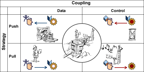
- Data coupling with push strategy: a computation prompts actors.
- Data coupling with pull strategy: an new input triggers the activity.
- Control coupling with push strategy: a local timer prompts actors.
- Control coupling with pull strategy: an external event triggers the process.
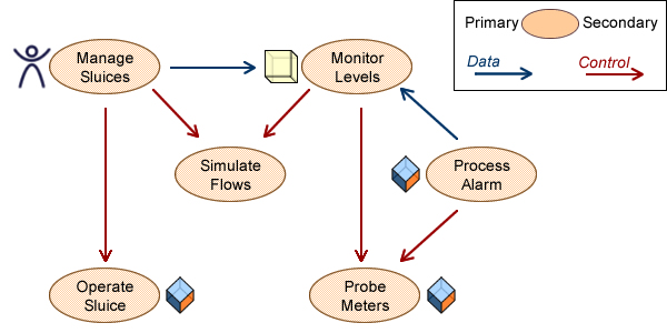
These basic options provide a patterns backbone tallying architectures capabilities, e.g:
- Control on functions is not constrained: simulate flows can be triggered from users or systems.
- Coupling rooted in primary actors should be compatible: alarms can control probes but can only send data to monitoring already controlled by a primary actor.
The next step is to align UC patterns with architecture capabilities.
UC Patterns & Architecture Capabilities
Since patterns are meant to provide principled solution blueprints, one would expect use cases patterns to shadow architecture capabilities. And since patterns apply to use cases as a whole, designated capabilities are meant to indiscriminately support all notional scenarii; said in other words, use cases patterns take a black-box view of actual execution paths.

Introducing such architecture based patterns is to significantly improve the transparency and modularity of use cases, e.g:
- The feasibility of all potential scenarii could be established up-front based on the capabilities of the selected UC pattern (11, 12, …).
- Constraints on scenarii could be specified by patterns, to be checked at development time, e.g data couplings tied to control ones (22).
Conversely, i.e from an enterprise perspective, UC patterns could be designed according to current or planned architecture capabilities.
But there is a hitch: if patterns are to mask the details of scenarii, they have to be organized according to capabilities.
So, if use case patterns are to be of any practicality, they have to ensure transparency and traceability between problems and solutions.
Patterns & Requirements
Patterns associate a left side for problems archetypes, to a right side for solution blueprints. Concerning use cases, problems can be unambiguously identified by triggering conditions: primary actor, triggering event, and associated business objects. Things are not so clear for solution blueprints because they have to deal with different kind of requirements (business, functional, and non-functional), the difficulty being compounded by the black-box constraint hiding the detail of scenarii.

As detailed elsewhere, rules constitute both the substance of requirements and the glue that holding them; patterns should therefore make a double distinction:
- Regarding the glue (i.e rules syntax), patterns should be defined according to the coupling profiles defined above.
- Regarding rules substance, patterns should set apart what belongs to business logic from what depends of supporting systems.
These rules are to be applied to use case contexts (aka sessions) which record initial circumstances (to remain unchanged until use case successful completion), and ensuing execution steps. Execution paths (aka scenarii) can then be governed by:
- Operational contexts, as indicated by triggering event (a), e.g web-based application or secured terminal.
- Agent identity and status, e.g authorizations, to be retrieved after actor’s authentication (c).
- The state of business objects (b).
- Sequencing of business operations (d).
- User options (e), e.g printing.
- Regulatory constraints (f).

But there is no reason to assume some innate alignment between the nature of rules (business, functional, or non functional) on one hand, and their scope (event, actor, business objects, users’ options) on the other hand, e.g:
- Depending on the business under consideration (e.g avionics vs insurance claims processing) requirements like data standards or response time may be seen as regulatory or technical, and consequently classified as functional or non functional.
- Secure payments may be contingent on the nature of operation (business requirements), amounts considered (functional), or encrypted communications (non functional).
Sorting out the different aspects of a problem is part and parcel of patterns design, which for use cases means factoring out functional requirements in order to map them to architecture capabilities.
Patterns & Threads
Insofar as architectures are concerned, the objective of patterns is to align applications designs on systems capabilities. Since architectures are first and foremost about shared resources and mechanisms, it ensues that use case patterns are to focus on the way resources and mechanisms are harnessed. On that account three basic categories can be defined:
- Abstract: use cases that are not meant to be triggered.
- Standalone: use cases that can be executed locally or instantly.
- Collaborative: use cases whose execution footprint cannot be determined ex ante.
Putting aside standalone applications (by definition not contingent on architectures), patterns should focus on the nature of shared resources and the constraints on collaboration mechanisms.
As noted above, patterns are meant to apply to use cases as a whole notwithstanding what may or may not happen along execution paths; to that end patterns are to be characterized by triggering conditions and execution threads (#), e.g:
- Roadside assistance is characterized by actor, triggering event, and the state of business objects.
- Invoicing and trucking are both concrete but the former can be executed on its own (data coupling) while the latter can only be triggered by roadside assistance (control coupling).
- Independent execution units (e.g invoice) may be triggered directly or from roadside assistance.
That is to be achieved using standard UML connectors and inheritance relationships.
Patterns & Structure: UC Connectors
While use case patterns are meant to be structured using UML <<include>> and <<extend>> connectors, there is no clear-cut distinction between them as both can be applied to shared activities, the former overlooking contingencies, the latter bringing up explicit branching conditions.
Given that patterns cannot condone with ambiguities, connectors’ semantics must be refined with regard to execution threads:
- <<include>> is to be associated with composition semantics: the included use case is to be controlled (hence instanciated) by the thread (#) of the including one.
- <<extend>> is to be associated with aggregation semantics: extending use case may or may not be triggered (hence instanciated) independently.
Along that understanding, patterns will use <<include>> connectors to indicate that all execution paths are to be controlled by the initial thread and run within the same session. Otherwise patterns will use <<extend>> connectors with an explicit business or functional extension point.

Patterns would also come with descriptors of triggering conditions and sessions.
Patterns & Abstraction: Inheritance
Abstract use cases and generalization have been intermittently part of UML, but they were never clearly defined. As for structures, they cannot be used by patterns without clear semantics.
Notionally, abstract UCs would describe activities never to be instanciated (aka triggered) on their own, which could be accounted for either by partial specifications or due to undefined triggering conditions.
The former reasoning is the one behind the definition of abstract classes, which could lead to some confusion between inheritance of structures and behaviors. More critically, defining partially specified activities as abstract would directly interfere with the semantics of <<extend>> connectors, as can be illustrated by system connections and users access:
One standard solution is to define a common use case controlling accesses for all users providing they can be identified before being subsequently (i.e during UC execution) qualified and authorized. Apparently, that could be done with <<include>> (a) or <<extend>> (b) connectors.

But the second option would not be possible with the semantic distinction suggested above for UC patterns, which specifies that use cases can only be extended from existing sessions.
A more generic approach (possibly with patterns) could try to “abstract” Open Session UC, e.g to cover a broader range of actors and identification mechanisms.
Understanding UC abstraction in terms of a partial specification to be <<included>> and run by the current thread will be inconsistent because there would be no concrete actor for the identification mechanisms (c).
By contrast, since inheritance connectors apply to types and not to instances (i.e execution threads), abstracted identification mechanisms are meant to be part of Manage Session and can be applied to triggering actors (d).
Such a clear distinction between the specification of threads (using connectors) and activities (using inheritance) should provide the basis of architecture-based UC patterns.
Patterns & Architectures
Use cases can seldom be considered in isolation, as if supported by standalone applications confined into single systems. They usually involve other use cases set across different architectures. Wrapping the whole into the same model raises practical as well as notional difficulties:
- From a practical point of view, models will have to host a mixed bag of legacy and planned use cases, with a corresponding mix of responsibilities.
- From a notional point of view, trying to consolidate use cases cannot be achieved without abandoning the black-box perspective and foraging deep into subsystems whose architecture may be still undefined.
The answer of Use Case 2.0 has been to introduce Slices, cutting into white-boxes in order to streamline use cases from requirements to realizations.
By contrast, patterns raise black-boxes to architecture level, bringing significant benefits both for business and system perspective:
- On the business side they foster pared down requirements focused on functional architecture.
- On the system side they provide a better understanding of business concerns together with their impact on system architecture.

In between, use case patterns provide with a way to check the consistency of use cases regarding functional architecture by checking stereotype compatibility of included use cases against including ones.
Further Reading
- Thread
- Use Cases & Ontologies
- Use Cases shouldn’t know about classes
- Use Cases & Action Semantics
- Business Processes & Use Cases
- Use Cases are Agile Tools
- Focus: Business Processes & Abstraction
- Focus: Business Cases for Use Cases
Dear Remy
I have followed the link and read Use Case Patterns. Does it relate to a book by that title?
You talked of Agent and Actor. Actor is defined in UML. Let know the definition of Agent and Source of definition. Is there also an explanation of the difference between Agent and Actor?
While describing the objectives of “Use Case Patterns” you mentioned two overlapping yet contrary Goals.
It appears that you are imagining them since two classes of Analysts are involved.
There is actually only ONE GOAL: Specify Business Requirements
It is actually created / reviewed / agreed to / used by a team of Business Analysts, Domain Experts, System Analysts, Software Professionals.
System Architecture is something that come up much later and a good statement of need or requirement can be cleared of any bias / implied solution / Architecture etc by simple techniques well publishes in TQM Literature (Juran in particular). There is no need to let bias persist if it is suspected.
There is nothing wrong with multiple interpretations of needs, clarifications, reformulation etc. as long as the team can arrive at acceptable set of statements. If some solution / architecture implications come up they can be detected and separated from Need, Goal, Means, Structures, Processes etc since their nature is known.
I use a set of home grown / privately used templates:
1 Statement of Project and Scope,
2 Use Case Diagram with adjunct table of “Actor, Use Case, Goal and Problems addressed”.
3 Use Case Description Template with three sections (the last one captures internal structures, processes and resources).
I do not know if the methods you suggested have equivalents. I will send them if you are willing to review and give me feedback.
Putcha V. Narasimham 30NOV10.
Thanks for your comments, I will try to answer: – The link “Use Case Patterns” comes under the title “representation patterns”, and it’s of my own. Otherwise you can look at “Use Cases, Patterns & Blueprints”, it’s helpful, but it’s something else.
– Regarding actors,agents, and roles, look at the page : http://caminao.wordpress.com/who-is-to-use-the-system/ http://caminao.wordpress.com/who-is-to-use-the-system/agents/ http://caminao.wordpress.com/who-is-to-use-the-system/roles/
– Regarding objectives, use cases should not be a dead end, there must be a continuity between requirements and the subsequent development artefacts, whatever the methods and/or terminology: iterative development, model driven, requirements engineering, use cases realization, lean processes, have your pick.
Finally, whereas I’m not aware of a similar approach, the reappraisal of requirements specification is coming under some attention and others may be looking in the same directions. I may add that I’ve published 3 books on that topic a few years ago (in French).