Domain Driven Design (DDD), the brainchild of Eric Evans, aims to map out system representations of business entities directly from business concepts and semantics.
How to conciliate bounded contexts and open minds (Balazs Szabo)
Four basic tenets are often put ahead to characterize DDD:
Layered architectures.
Aggregates and threads of continuity and identity.
Bounded contexts.
Ubiquitous language supporting the communication between business domains and software representations.
If the meaning and benefits of layers and aggregates are widely understood, there is less of a consensus about practical implementation of bounded contexts and ubiquitous languages.
Architecture Layers
All too often, modelers overlook the difference between descriptive and prescriptive models, the former depicting business environments and objectives, the latter their symbolic representations in systems. Unfortunately, this seemingly benign neglect seems to imply that descriptive models have no other purpose than supporting the development of systems, which can subsequently stand on their own. But what may once have been a safe assumption is now a very hazardous one considering that today’s IT systems must be weaved with enterprise environment and accommodate continuously to its changes.
Feeding development processes is not the only purpose of descriptive models.
On that regard Domain Driven Design seems inconclusive: on one hand it insists upon the tie between concepts and implementations, on the other hand it makes a clear distinction between concepts (roots and aggregates), and their use (contexts). Setting DDD layers with regard to enterprise architecture could help to clarify the point.
With regard to software (as opposed to enterprise) architecture, DDD identifies four layers: users interfaces (or presentation), applications, domains (or models), and infrastructures. Of these, the domain layer seems to be the only one unambiguously set apart, definitions of the others leaving room for overlaps; but potential qualms can be easily remedied by introducing formal criteria:
Presentation: non shared processing of I/O.
Application: shared processing of transient representations
Domain: shared access to persistent representations
Infrastructure: shared access to services.
Architecture Functional layers understood as PIM artifacts.
Furthermore, these layers are best understood when associated with the platform independent models (PIMs) of the model driven architecture (MDA) framework.
Aggregates & Roots
The distinction between the identity and structure of objects on one hand, features semantics and use on the other hand, is arguably a core tenet of DDD as it brings together objects designs and systems architectures.
With regard to objects design, aggregates to be accessed through a single root (#) guarantee the continuity and integrity of the threads anchoring business entities to their symbolic counterparts.
With regard to systems architectures, features of business entities surrogates can be shared across domains, each according to their own semantics, as epitomized by persons in the example below.
Roots anchor identified (#) persons to their symbolic surrogates
Yet, the fact is that approach combines object with aspect oriented designs and its implementation at architecture level could come with serious drawbacks when functional facets are to be shared across domains. That’s where bounded contexts intervene.
Bounded Contexts
Contexts are introduced to conciliate continuity and integrity, managed through aggregates, and semantics and functional accesses, managed through contexts; bounded contexts (BCs) are ones with shared business entities. Adding to the example above, person usually appears in different functional contexts subject to specific responsibilities, with one and only one with explicit responsibility on aggregates (#).
Bounded contexts are used to distinguish between identification and integrity, managed through aggregates, and semantics and use, managed through contexts.
But as sound and useful as bounded contexts may be conceptually, their implementation is mostly entrusted to maps and best practices. Since the way shared business domains are managed by systems is arguably a key success factor of enterprise architectures, the lack of principled implementation schemes leaves the conceptual gap between business domains and software designs unaccounted for. That would be the purpose of ubiquitous languages (UL).
Ubiquitous or Domain Specific Languages.
The explicit objective of ubiquitous languages is to bring under a common semantic roof domain analysis and software design, and so to tie concepts and implementations. But that very endeavor may also be seen as controversial, shallow, and confusing:
Controversial: bringing together concepts and implementations appears to contradict OO principles as well as layered architectures.
Shallow: the so-called languages (as many as domains ?) are in fact just lists of entities and operations, without grammar or unifying semantics.
Confusing: they are supposedly derived from models, which would suggest specificity instead of ubiquity; that understanding would also belie the customary assumption that models are built with modeling languages.
One way out of the conundrum could be to see ubiquitous languages as variants of domain specific ones whose explicit objective is precisely to tie concepts with implementations. But that option would bypass the issue of principled BC design, and more generally the relationship between business domains, systems architectures, and software designs.
Open concepts are modeling artifacts whose semantics can be shared by business domains and systems functional architectures. For that purpose they have to meet standard OO principles:
Open-Closed Principle (OPC): open concepts should have no reason to change, they can only be refined. In other words open concepts are meant to be specialized, but not generalized. That ensures that the semantics of sub-types defined by different projects cannot be modified.
Substitution Principle (LSP): sets of instances denoted by specialized concepts are subsets of the sets denoted by more general ones. That ensures that individuals are consistently identified across projects.
Dependency-Inversion principle (DIP): higher levels semantics are defined independently of lower levels. That ensures that the semantics of sub-types are consistently, but not necessarily uniformly, defined across projects.
Interface-Segregation Principle (ISP): semantics and features are congruent, i.e all features are meaningful for whoever is using the concept. That ensures that there is no overlapping of semantics even when subsets of individuals overlap.
Assuming these criteria can be fulfilled, open concepts can be used as a modeling glue between bounded contexts overlaps.
Open concepts for entities (aka roots):
Structural inheritance means that the targeted entities (i.e shared between contexts) inherit both structures and aspects: parties are a subset of social agents.
Functional inheritance means that the targeted entities inherit all the aspects whatever the identified structure: an organization has all the features of a collective agent but is not necessarily identified as such.
How to consolidate contexts overlaps using open concepts
Open concepts for aspects (aka features):
Structural inheritance is equivalent to composition, i.e inherited aspects are bound to domain individuals whatever their structure: symbolic references are an intrinsic component of products but can be used in any kind of domain.
Functional inheritance is equivalent to aggregation, i.e inherited aspects are not bound to domain individuals: business roles can combine different ones.
On a broader perspective, using open concepts to consolidate the overlaps between bounded contexts enables the formal verification of models, not only for internal consistency but also with regard to best practices. And best practices can be translated into functional (aka representation) patterns formally defined in terms of open concepts.
Following the recent publication of a new standard for conceptual modeling of automation systems (Object-Process Methodology (ISO/PAS 19450:2015) it may be interesting to explore how it relates to abstraction and meta-models.
Meta-models are drawn along lean abstraction scales (Oskar Schlemmer )
Models & Meta Models
Just like models are meant to describe sets of actual instances, meta-models are meant to do the same for sets of modeling artifacts independently of their targets. Along that reasoning, conceptual modeling of automation systems could be achieved either with a single language covering all aspects, or with a meta-language dealing with different sets of models, e.g MDA’s computation independent, platform independent, and platform specific models.
Two alternative options for the modeling of automation systems: unified language, or a meta language covering technical (e.g PSMs), functional (e.g PIMs), and business (e.g CIMs) scopes.
Given a model based engineering framework (e.g MDA), meta-models are generally used to support downstream models transformation targeting designs and code. But when upstream conceptual models are concerned, the challenge is to tackle the knowledge-to-systems transition. For that purpose some shared modeling roof is required for the definition of the symbolic footprint of the targeted business in the automation system under consideration.
Symbolic Footprint
Given that automation systems are meant to manage symbolic objects (aka surrogates), one should expect the distinction between actual instances and their symbolic representations to be the cornerstone of corresponding modeling languages. Along that reasoning, modeling of automation systems should start with the symbolic representation of actual business footprints, namely: the sets of objects, events, and processes, the roles played by agents (aka active objects), and the description of the associated states and rules. Containers would be added for the management of collections.
Automation systems modeling begins with the symbolic representation by systems of actual instances of business related objects and phenomena.
Next, as illustrated by the Object/Agent hierarchy, business worlds are not flat but built from sundry structures and facets to be represented by multiple levels of descriptions. That’s where abstractions are to be introduced.
Abstraction & Variants
The purpose of abstractions is to manage variants, and as such they can be used in two ways:
For partial descriptions of actual instances depending on targeted features. That can be achieved using composition (for structural variants) and partitions (for functional ones).
As hierarchies of symbolic descriptions (aka types and sub-types) subsuming variants identified at instances level.
On that basis the challenge is to find the level of detail (targeted actual instances) and abstraction (symbolic footprint) that will best describe supporting systems functionalities. Such level will have to meet two conditions:
A minimal number of comprehensive and exclusive categories covering the structural variants of the sets of instances to be uniformly, consistently, and continuously identified by both enterprise and supporting systems.
A consistent but adjustable set of types and sub-types anchored to the core structural categories and covering the functional variants .
Climbing up and down abstraction ladders looking for right levels is arguably the critical part of conceptual modeling, but the search will greatly benefit from the distinction between models and meta-models. Assuming meta-models are meant to ignore domain specific features altogether, they introduce a qualitative gap on abstraction scales as the respective hierarchies of models and meta-models are targeting different kind of instances. The modeling of agents and roles epitomizes the benefits of that distinction.
Abstraction & Meta Models
Taking customers for example, a naive approach would use Customer as a modeling type inheriting from a super-type, e.g Party. But then, if parties are to be uniformly identified (#), that would preclude any agent for playing multiple roles, e.g customer and supplier.
A separate description of parties and roles would clearly be a better option as it would unify the identification of the former without introducing unwarranted constraints on the latter which would then be defined and identified as the realization of a relationship played by a party.
Not surprisingly, that distinction would also be congruent with the one between models and meta-model:
Meta-models will describe generic aspects independently of domain-specific considerations, in particular organizational context (units and roles) and interactions with systems (a).
Models will define Staff, Supplier and Customer according to the semantics of the business considered (b).
Composition, partitions and specialization can be used along two different abstraction scales.
That distinction between abstraction scales can also be applied to the conceptual modeling of automation systems.
Abstraction Scales & Conceptual Models
To begin with definitions, conceptual representations could be used for all mental constructs, whereas symbolic representations would be used only for the subset earmarked for communication purposes. That would mean that, contrary to conceptual representations that can be detached of business and enterprise practicalities, symbolic representations are necessarily built on design, and should be assessed accordingly. In our case the aim of such representations would be to describe the exchanges between business processes and supporting systems.
That understanding neatly fits the conceptual modeling of automation systems whose purpose would be to consolidate generic and business specific abstraction scales, the former for symbolic representations of the exchanges between business and systems, the latter symbolic representation of business contents.
At this point it must be noted that the scales are not necessarily aligned in continuity (with meta-models’ being higher and models’ being lower) as their respective ontologies may overlap (Organizational Entity and Party) or cross (Function and Role).
Toward an Ontological Framework for Enterprise Architectures Modeling
Along an analytic perspective, ontologies are meant to determine the categoriesthat can comprehensively and consistently denote the instances of a domain under consideration; applied to enterprise concerns that would entail:
Thesaurus: for the whole range of terms and concepts.
Documents: for documents with regard to topics.
Business: for enterprise organization and business objects and activities.
Engineering: for systems surrogates associated to enterprise organization and business objects and activities
Ontologies provide a common conceptual framework for models and meta-models
That would open the door to a seamless integration of business intelligence, systems engineering, knowledge management, and decision-making.
Assuming patterns are meant to chart the path from problems to solutions, and given the foundational contribution of the Gang of Four (GoF), it may help to look at functional (aka representation) patterns backward from the perspective of the now well established solutions framework (aka design patterns).
Matching Patterns (M.Kippenberger)
Patterns & Models
Patterns are handrails from stereotyped problems to well known and tested solutions, bringing the benefits of reuse for costs, quality, and traceability. Set within the Model Driven Architecture, patterns can be regrouped depending on their source and target:
Functional patterns deal with the representation of business objects and activities by system symbolic surrogates. They stand between computation and platform independent models. Whereas functional patterns are not to be confused with business patterns (used with CIMs), they are also known as analysis patterns when targeting PIMs.
Design patterns deal with the implementation of symbolic surrogates as software components. They stand between platform independent and platform specific models.
Patterns and MDA layers
As it happens, there is a striking contrast between the respective achievements for design and functional (or analysis) patterns, the former, firmly set up by the pivotal work of the GoF, is nowadays widely and consistently applied to software design; the latter, frustrated by the medley of requirements capture, remain fragmented and confined to proprietary applications. Given that discrepancy, it may be worth to look in the rear-view mirror and consider functional patterns from the perspective of design ones.
Objects, Classes, & Types
Design patterns are part and parcel of the object oriented (OO) approach and built on some of its core tenets, in particular:
Favor object composition over class inheritance.
Program to an interface, not an implementation.
Whereas the meaning of classes, implementation, and inheritance is specific to OO design, the principles can nonetheless bear upon analysis providing they are made to apply to types and composition, whose semantics have a broader scope. To begin with, if classes describe the software implementation of symbolic objects, and inheritance the relationships between them, types only pertain to their functional capabilities. As a corollary, the semantics of inheritance and composition makes no difference with regard to types, as opposed to classes. The lesson for functional patterns would therefore to favor types whenever possible, i.e when functional capabilities doesn’t depend on identities. Then, “programming to interfaces” would translate (for functional patterns) into describing communications between types. That approach being best represented by aspect oriented analysis. Not by chance, the lessons drawn above appear to be directly supported by the two criteria used by the the GoF to classify design patterns: scope and purpose. With regard to scope, class patterns deal with inheritance relationships between static descriptions fixed at compile-time, while object patterns deal also with relationships between instances which can be changed at run-time. With regard to purpose, creational patterns deal with objects instanciation, structural ones carry on with composition, and behavioral ones with algorithms and responsibilities.
Design Patterns Catalog
The corresponding entries can be summarily described as:
Class/Creational: for new identified instances.
Object/Creational: for new parts of identified instances.
Class/Structural: for mixing interfaces using inheritance.
Object/Structural: for mixing interfaces using composition.
Class/Behavioral: for the definition of algorithms.
Object/Behavioral: for the collaboration between instances.
The next step would be to induce a catalog of functional patterns from those entries.
Inducing a Catalog of Functional Patterns
Leveraging the GoF’s design patterns, the objective is to spread the benefits upstream to the whole of the modeling process through a transparent mapping of functional and design patterns. And that could be achieved by inducing a functional catalog from its design equivalent. With regard to scope, the objective would be to factor out the architectural impact of requirements. Hence the distinction between architecture patterns dealing with business entities and processes consistently identified at enterprise and system levels, and aspect patterns dealing with features that can be managed separately. With regard to purpose the same semantics can be applied: creational patterns deal with objects instanciation, structural ones carry on with their composition and features, and behavioral ones with algorithms and responsibilities.
Functional Patterns Catalog: examples
Architecture/Creational: for the mapping of business entities to their software surrogates. For instance, customers must be identified as parties (architecture/creational) before being fleshed out with specific features.
Aspect/Creational: for the intrinsic components of identified business entities. For instance, once created and identified as a customer, a foreign one is completed with the specific mandatory features of foreigners.
Architecture/Structural: for inherited (i.e intrinsic) features of identified business entities. For instance, foreign sales inherit specific invoice features.
Aspect/Structural: for associated (intrinsic or otherwise) features of identified business entities. For instance, foreign sales delegate invoicing in foreign currencies.
Architecture/Behavioral: for the definition business rules attached to entities and managed by business domains. For instance invoicing rules are specialized for foreign currencies.
Aspect/Behavioral: for the definition of collaboration between entities independently of business domains. For instance allocating responsibilities at run-time depending on the invoice.
As can be seen with the MDA diagram above, this catalog is neutral as its entries are congruent with the categories used by the main modeling methodologies : use cases, domains, business rules, services, objects, aspects, etc.
Computation Independent Models (CIMs) describe business objects and activities independently of supporting systems.
Platform Independent Models (PIMs) describe systems functionalities independently of platforms technologies.
Platform Specific Models (PSMs) describe systems components as implemented by specific technologies.
Since those layers can be mapped respectively to enterprise, functional, and technical architectures, the question is how to make heads or tails of the driving: should architectures be set along model layers or should models organized according architecture levels.
A Dog Making Head or Tail (Judy Kensley McKie)
In other words, has some typo reversed the original “architecture driven modeling” (ADM) into “model driven architecture” (MDA) ?
Wrong Spelling, Right Concepts
A confusing spelling should not mask the soundness and relevance of the approach: MDA model layers effectively correspond to a clear hierarchy of problems and solutions:
Computation Independent Models describe how business processes support enterprise objectives.
Platform Independent Models describe how systems functionalities support business processes.
Platform Specific Models describe how platforms implement systems functionalities.
MDA layers correspond to a clear hierarchy of problems and solutions
That should leave no room for ambiguity: regardless of the misleading “MDA” moniker, the modeling of systems is meant to be driven by enterprise concerns and therefore to follow architecture divides.
Architectures & Assets Reuse
As it happens, the “MDA” term is doubly confusing as it also blurs the distinction between architectures and processes. And that’s unfortunate because the reuse of architectural assets by development processes is at the core of the MDA framework:
Business objects and logic (CIM) are defined independently of the functional architectures (PIM) supporting them.
Functional architectures (PIM) are defined independently of implementation platforms (PSM).
Technical architecture (PSM) are defined independently of deployment configurations.
MDA layers coincide with categories of reusable assets
Under that perspective the benefits of the “architecture driven” understanding (as opposed to the “model driven” one) appear clearly for both aspects of enterprise governance:
Systems governance can be explicitly and transparently aligned on enterprise organization and business objectives.
Business and development processes can be defined, assessed, and optimized with regard to the reuse of architectural assets.
With the relationship between architectures and processes straightened out and architecture reinstated as the primary factor, it’s possible to reexamine the contents of models used as hinges between them.
Languages & Model Purposes
While engineering is not driven by models but by architectures, models do describe architectures. And since models are built with languages, one should expect different options depending on the nature of artifacts being described. Broadly speaking, three basic options can be considered:
Versatile and general modeling languages like UML can be tailored to different contexts and purposes, along development cycle (requirements, analysis, design) as well as across perspectives (objects, activities, etc) and domains (banking, avionics, etc)
Non specific business modeling languages like BPM and rules-based languages are meant to be introduced upfront, even if their outcome can be used further down the development cycle.
Domain specific languages, possibly built with UML, are also meant to be introduced early as to capture domains complexity. Yet, and contrary to languages like BPM, their purpose is to provide an integrated solution covering the whole development cycle.
Languages: general purpose (blue), process or domain specific (green), or design (brown).
As seen above for reuse and enterprise architecture, a revised MDA perspective clarifies the purpose of models and consequently the language options. With developments “driven by models”, code generation is the default option and nothing much is said about what should be shared and reused, and why. But with model contents aligned on architecture levels, purposes become explicit and modeling languages have to be selected accordingly, e.g:
Domain specific languages for integrated developments (PSM-centered).
BPM for business specifications to be implemented by software packages (CIM-centered).
UML for projects set across system functional architecture (PIM-centered).
The revised perspective and reasoned association between languages and architectures can then be used to choose development processes: projects that can be neatly fitted into single boxes can be carried out along a continuous course of action, others will require phased development models.
Enterprise Architecture & Engineering Processes
Systems engineering has to meet different kinds of requirements: business goals, system functionalities, quality of service, and platform implementations. In a perfect (model driven engineering) world there would be one stakeholder, one architecture, and one time-frame. Unfortunately, requirements are usually set by different stakeholders, governed by different rationales, and subject to changes along different time-frames. Hence the importance of setting forth the primary factors governing engineering processes:
Planning: architecture levels (business, systems, platforms) are governed by different time-frames and engineering projects must be orchestrated accordingly.
Communication: collaboration across organizational units require traceability and transparency.
Governance: decisions across architecture levels and business units cannot be made upfront and options and policies must be assessed continuously.
Those objectives are best supported when engineering processes are set along architecture levels:
Enterprise Architecture & Processes
Requirements: at enterprise level requirements deal with organization and business processes (CIMs). The enterprise requirements process starts with portfolio management, is carried on with systems functionalities, and completed with platforms operational requirements.
Problems Analysis: at enterprise level analysis deals with symbolic representations of enterprise environment, objectives, and activities (PIMs). The enterprise analysis process starts with the consolidation of symbolic representations for objects (power-types) and activities (scenarii), is carried on with functional architectures, and completed with platforms non-functional features. Contrary to requirements, which are meant to convey changes and bear adaptation (dashed lines), the aim of analysis at enterprise level is to consolidate symbolic representations and guarantee their consistency and continuity. As a corollary, analysis at system level must be aligned with its enterprise counterpart before functional (continuous lines) requirements are taken into account.
Solutions Design: at enterprise level design deals with operational concerns and resources deployment. The enterprise design process starts with locations and resources, is carried on with systems configurations, and completed with platforms deployments. Part of it is to be supported by systems as designed (PSMs) and implemented as platforms. Yet, as figured by dashed arrows, operational solutions designed at enterprise level bear upon the design of systems architectures and the configuration of their implementation as platforms.
When engineering is driven by architectures, processes can be devised depending on enterprise concerns and engineering contexts. While that could come with various terminologies, the partitioning principles will remain unchanged, e.g:
Agile processes will combine requirements with development and bypass analysis phases (a).
Projects meant to be implemented by Commercial-Off-The-Shelf Software (COTS) will start with business requirements, possibly using BPM, then carry on directly to platform implementation, bypassing system analysis and design phases (b).
Changes in enterprise architecture capabilities will be rooted in analysis of enterprise objectives, possibly but not necessarily with inputs from business and operational requirements, continue with analysis and design of systems functionalities, and implement the corresponding resources at platform level (c).
Projects dealing with operational concerns will be conducted directly through systems design of and platform implementation (d).
Examples of process templates depending on objectives and contexts.
To conclude, when architecture is reinstated as the primary factor, the MDA paradigm becomes a pivotal component of enterprise architecture as it provides a clear understanding of architecture divides and dependencies on one hand, and their relationship with engineering processes on the second hand.
Reusing artifacts means using them in contexts that are different of their native ones. That may come by design, when specifications can anticipate on shared concerns, or as an afterthought, when initially unexpected similarities are identified later on.
Economics of Reuse (Sergio Silva)
Planned or opportunistic, reuse brings benefits in terms of costs, quality, and continuity:
Cost benefits are most easily achieved for component engineering but may also be obtained upstream with model reuse and patterns.
Quality benefits are first and foremost rooted at model level, especially when components implementation is supported by automated tools.
Continuity benefits are to be found both along the business (semantics and business rules) and engineering (functional architecture and platform implementations) perspectives.
Reuse policies may also bring positive externalities by inducing a comprehensive approach to software design.
Yet, those policies will usually entail costs and may as well bear negative externalities:
Artifacts designed for reuse are usually most costly to develop, even if part of additional costs should be ascribed to quality management.
Excessive enforcement policies may significantly hamper projects ability to meet business needs in time.
Managing reusable assets usually induces overheads.
In order to assess those policies, economics of reuse must be set across business, engineering or architecture perspectives:
Business perspective: how to factor out and reuse artifacts associated with the knowledge of business domains when system functionalities or platforms are modified.
Engineering perspective: how to reuse development artifacts when business contents or system platforms are modified.
Architecture perspective: how to use system components independently of changes affecting business contents or development artifacts.
That can be achieved by managing development assets along model driven architecture: CIMs for business and enterprise architecture, PIMs for systems functional architecture, and PSMs for systems technical architecture.
Contexts & Concerns
Whatever their inception, reused artifacts are meant to be used independently of their native context and concerns: opportunistic reuse will map a specific purpose to another one, planned reuse will map a shared concern to a specific purpose. As a corollary, reuse policies must be supported by some traceability mechanism linking concerns and purposes across contexts and architectures.
From the enterprise perspective, the problem is to reuse the knowledge of business domains and processes. For that purpose different mechanisms can be considered:
The simplest solution is to reuse generic components, with the business knowledge directly transferred through parameters.
Similarly, business rules can be separately edited and managed in business contexts before being executed by system components.
One step further, business semantics and rules can be fenced off with domains and applied to different objects and applications.
Finally, models of business objects and processes can be capitalized and managed as reusable assets.
Reuse Policies with Model Driven Architecture
Once business knowledge is duly capitalized as functional assets, they can be reused along the engineering perspective:
System functionalities: functional patterns are (re)used to map functional requirements to functional architecture, and services are (re)used to support business processes.
Software implementations: Component-based development and information hiding.
Along the architecture perspective information hiding is generalized to systems, and reuse is masked by the definition of services.
It must be noted that, contrary to misleading similarities, refactoring is the opposite of reuse: instead of building from well understood and safe artifacts, it tries to extract some reusable chunks from opaque and unsafe components.
Knowledge Reuse
Enterprise and business knowledge may affect the full scope of system functionalities: boundaries (e.g users authorizations), controls (e.g accounting rules), and persistency (e.g consistency constraints). Whereas there isn’t much to argue about the benefits of reusing enterprise and business knowledge, costs may significantly diverge depending on the way corresponding assets are managed:
Domain specific knowledge are rooted at requirements level. That’s typically achieved when use cases are introduced to describe how systems are meant to support business processes. With different use cases targeting different aspects of the same business objects and processes, overlaps must be identified and factored out in order to be reused across processes.
Business knowledge may also be global, i.e shared at enterprise architecture level, defining objectives, assets and organization associated with the continuity of corporate identity and business capabilities within a regulatory and market environment.
Use cases access to respectively shared (a,b) and specific (c,d) knowledge for objects and application domains
In any case, the challenge is to map business knowledge to system models, more precisely to embed reused descriptions of business objects and process to corresponding development artifacts. At architecture level the mapping should target objects or processes identities, at domain level the focus will be on aspects and views.
As epitomized by service oriented architectures, business architectures can be mapped to system ones through delegation, either directly (business processes calling on services), or indirectly (collaboration between services). That will establish a clear distinction between shared (aka global) and domain specific knowledge, and consequently between respective economics of reuse.
Given that shared knowledge must be reused across domains and applications, there can be no argument about benefits. That will be achieved by a messaging model built on a need-to-know basis. And since such model is an intrinsic feature of the functional architecture, it incurs no additional overheads.
Specific knowledge for its part is managed at domain level and therefore masked behind services interfaces. Whatever reuse occurs there remains local and an intrinsic part of domain design.
Knowledge Reuse through services (a), boundaries (b), controls (c), and entities (d).
Things are not so clear when business knowledge is not managed by services but distributed across domains, mixing specific and global knowledge. Managing reusable assets would be easy were the distinction between business and functional requirements to coincide with the one between shared and specific knowledge; unfortunately that’s seldom the case, and requirements, functional or business, will have to be sorted out at architecture or design level.
Whereas Service Oriented Architectures (SOA) put functionalities in the driving seat, Enterprise Application Integration (EAI) gives the lead to applications for which it provides adapters. As maintenance of integration adapters is a very poor substitute for knowledge management, reuse is mostly limited to legacy applications.
Maintaining adapters across layers of applications induces significant overheads
At design level knowledge is weaved into canonical data models (entities), functional architectures (controls), and user interfaces frameworks (boundaries).
Mixed concerns: business requirements can be specific, functional ones can be global.
On one hand, tracing reuse to requirements may be problematic as they are by nature concrete and unstructured, hence not the best support for generalization or the factoring out of shared features. Assuming business analysts can nonetheless separate reusable wheat from specific chaff, knowledge management at this level will require a dedicated framework supporting comprehensive and differentiated traceability. Additional overheads will have to be taken into account and compared to potential benefits.
On the other hand, canonical data models and functional architectures are meant to provide unified views of shared objects and semantic domains. Yet, canonical models are by nature unwieldy as they carve structures, features, and connections of business objects, without clear mechanisms to combine shared and specific knowledge. As a corollary, their use may reduce flexibility, and their management usually induces significant overheads.
Artifacts Reuse
With enterprise and business knowledge capitalized as development assets, the engineering case for reuse may appears indisputable, but business cases are often much more controversial due to large overheads and fleeting returns. Taking cues from Barry Boehm (“Managing Software Productivity and Reuse”), here are some of the main pitfalls of artifacts reuse:
Repository delusion: knowledge being by nature contextual, its reuse is driven by circumstances and purposes; as a consequence the availability of large repositories of development assets will probably be ignored without clear pointers rooted in contexts and concerns.
Confusion between components (or structures) and functionalities (or interfaces): under the influence of the object oriented paradigm, the distinction between objects and aspects is all too often forgotten. That’s unfortunate as this difference is congruent with the one between business objects on one hand, business operations on the other hand.
Over generalization: reuse is usually achieved by factoring out useful aspects or factoring off useless ones. In both cases the temptation is to repeat the operation until nothing could be added to the scope. Such “flight for abstraction” will inevitably overtake the proper level of reuse and begets models void of any anchor to business relevancy.
Scalability: while reuse is about separation of concerns and complexity management, those two criteria don’t have to pull in the same direction. When they don’t, variants will be dispersed across artifacts and their processing will suffer a combinatorial explosion if the system has to be scaled up.
Obsolescence: shelf lives of development assets can be defined by each or both business or technical relevancy. Assuming spans either coincide or are managed independently, they should be explicitly taken into account before any reuse.
Those obstacles can be managed providing that models:
Provide some built-in traceability mechanisms between knowledge and artifacts.
Sorting out reuse concerns with differentiated inheritance.
Economics of Reuse and Sustainable Development
Sustainable system development is the ability to meet present business requirements while enhancing system capability to support future ones. Clearly reuse is not the only factor of sustainability, with architectures, returns, and risk management being pivotal. But the economics of reuse encompass most of other factors.
Architectures are clearly first to be considered, as epitomized by MDA:
Reuse of development assets rooted in enterprise architecture is not an option: system functionalities are meant to support business processes as they are (a).
At the other end of the development process, reuse of software designs and components across technical architectures should bring benefits in quality and costs (c).
In between reuse of system functionalities is necessary to guarantee the robustness and continuity of functional architectures; it should also leverage the benefits of reuse of enterprise and development assets (b).
Reuse of models is at the core of the MDA framework
Regarding returns, reuse through generic components, rules engines, or semantic domains can be directly supported by development tools, bypassing explicit models of functional architectures. That makes their costs/benefits analysis both simpler and well circumscribed. That is not the case for system functionalities which stand at the hub of perspectives. As a consequence, costs/benefits should be analyzed as a whole:
Regarding business assets, a clear distinction must be maintained between specific and shared knowledge, reuse being considered for the latter only.
Regarding the reuse of business assets as functional ones, services clearly offer the best returns. Otherwise costs/benefits are to be assessed, from reuse of vocabulary and semantics domains (straightforward, limited overheads), to canonical models and enterprise application integration (contingent, significant overheads).
Economics of reuse will ultimately be set by traceability mechanisms linking enterprise and business knowledge on one hand, components designs on the other hand. Even for services (c), if at a lesser degree, the business case for reuse will be decided by leveraged benefits and non cumulative costs. Hence the importance of maintaining the distinction between identified structures and associated aspects from business (a) and functional (b) requirements, to components interfaces (d) and structures (e).
Maintaining the distinction between structures and aspects from business (a) and functional (b) requirements, to components interfaces (d) and structures (e).
Finally, reuse may also play a significant role in risk management, especially when risks are managed according to their source:
Changes in business contexts can usually occurs along two frequency waves: short, for market opportunities, and long, for an organization’s continuity. Associated risks could be better managed if corresponding knowledge were managed accordingly.
System architectures are meant to evolve in synch with organization continuity; were technological environment or corporate structures subject to unexpected changes, reusable functional assets would be of great help.
Given that enterprise IT can no longer be self-contained and operate in isolation, reusable designs may provide buffers to technological risks and help exploiting unexpected business opportunities.
Reuse of development artifacts can come by design or as an afterthought. While in the latter case artifacts may have been originally devised for specific contexts and purposes, in the former case they would have been originated by shared concerns and designed according architectural constraints and mechanisms.
Reinventing the Wheel ? (Ready-made, M. Duchamp)
Architectures for their part are about stable and sound assets and mechanisms meant to support activities which, by nature, must be adaptable to changing concerns. That is precisely what reusable assets should be looking for, and that may clarify the rationale supporting models and languages:
Why models: to describe shared (i.e reused) artifacts along development processes.
Why non specific languages: to support the sharing of models across business domains and organizational units.
Why model layers: to manage reusable development assets according architectural concerns.
Reuse Perspective: Business Domains vs Development Artifacts
As already noted, software artifacts incorporate contents from two perspectives:
Domain models describe business objects and processes independently of the way they are supported by systems.
Development models describe how to design and implement system components.
Artifacts reflect external as well as development concerns.
As illustrated by agile methods and domain specific languages, that distinction can be ignored when applications are self-contained and projects ownership is shared. In that case reusable assets are managed along business domains, functional architectures are masked, and technical ones are managed by development tools.
Otherwise, reusable assets would be meaningless, even counterproductive, without being associated with clearly defined objectives:
Domain models and business processes are meant to deal with business objectives, for instance, how to assess insurance premiums or compute missile trajectory.
System functionalities lend a hand in solving business problems. Use cases are widely used to describe how systems are to support business processes, and system functionalities are combined to realize use cases.
Platform components provide technical solutions as they achieve targeted functionalities for different users, within distributed locations, under economic constraints on performances and resources.
Context and purpose of reusable assets
Whatever the basis, design or afterthought, reusing an artifact comes as a solution to a specific problem: how to support business requirements, how to specify system functionalities, how to implement system components. Describing problems and solutions along architecture layers should therefore be the backbone of reusable assets management.
Model and Architecture Layers
According model driven architecture principles, models should be organized around three layers depending on contents:
Computation independent models (CIMs) describe business objects and processes independently of the way they are supported by system functionalities. Contents are business specific that can be reused when functional architectures are modified (a). Business specific contents (e.g business rules) can also be reused when changes do not affect functional architectures and may therefore be directly applied to platform specific models (c).
Platform independent models (PIMs) describe system functionalities independently of supporting platforms. They are reused to design new supporting platforms (b).
Platform specific models (PSMs) describe software components. They are used to implement software components to be deployed on platforms (d).
Model and Architecture Layers
Not by chance, invariants within model layers can also be associated with corresponding architectures:
Enterprise architecture (as described by CIMs) deals with objectives, assets and organization associated with the continuity of corporate identity and business capabilities within a regulatory and market environment.
Functional architecture (as described by PIMs) deals with the continuity of systems functionalities and mechanisms supporting business processes.
Technical architecture (as described by PSMs) deals with the feasibility, interoperability, efficiency and economics of systems operations.
That makes architecture invariants the candidates of choice for reusable assets.
Enterprise Architecture Assets
Systems context and purposes are set by enterprise architecture. From an engineering perspective reusable assets (aka knowledge) must include domains, business objects, activities, and processes.
Domains are used to describe the format and semantics of elementary features independently of objects and activities.
Business objects identity and consistency must be maintained along time independently of supporting systems. That’s not the case for features and rules which can be modified or extended.
Activities (and associated roles) describe how business objects are to be processed. Semantics and records have to be maintained along time but details of operations can change.
Business processes and events describe how activities are performed.
Enterprise Architecture Assets (anchors and semantic domains)
As far as enterprise architecture is concerned, structure and semantics of reusable assets should be described independently of system modeling methods.
Structures can be unambiguously described with standard connectors for composition, aggregation and reference, and variants by subsets and power-types, both for static and dynamic partitions.
With regard to business activities, semantics are set by targets:
Processing of physical objects.
Processing of notional objects.
Agents decisions.
Processing of events.
Computations.
Control of processes execution.
Regarding business objects, semantics are set by what is represented:
State of physical objects.
State of notional object.
History of roles.
Events.
Computations.
Execution states.
Enterprise Architecture Assets (with variants and stereotypes)
Enterprise assets are managed according identification, structure, and semantics, as defined along a business perspective. When reused as development artifacts the same attributes will have to be mapped to an engineering perspective.
Use Cases: A bridge between Enterprise and System Architectures
Systems are supposed to support the continuity and consistency of business processes independently of platforms technologies. For that purpose two conditions must be fulfilled:
Identification continuity of business domains: objects identities are kept in sync with their system representations all along their life-cycle, independently of changes in business processes.
Semantic continuity of functional architectures: the history of system representations can be traced back to associated business operations.
Hence, it is first necessary to anchor requirements objects and activities to persistency and functional execution units.
Reusing persistency and functional units to anchor new requirements to enterprise architecture.
Once identities and semantics are properly secured, requirements can be analyzed along standard architecture levels: boundaries (transient objects, local execution), controls (transient objects, shared execution), entities (persistent objects, shared execution).
The main objective at this stage is to identify shared functionalities whose specification should be factored out as candidates for reuse. Three criteria are to be considered:
System boundaries: no reusable assets can stand across systems boundaries. For instance, were billing outsourced the corresponding activity would have to be hid behind a role.
Architecture level: no reusable assets can stand across architecture levels. For instance, the shared operations for staff interface will have to be regrouped at boundary level.
Coupling: no reusable asset can support different synchronization constraint. For instance, checking in and out are bound to external events while room updates and billing are not.
Using stereotypes to identify shared functionalities along architecture levels
It’s worth to note that the objectives of requirements analysis do not depend on the specifics of projects or methods:
Requirements are to be anchored to objects identities and activities semantics either through use cases or directly.
Functionalities are to be consolidated either within new requirements and/or with existing applications.
The Cases for Reuse
As noted above, models and non specific languages are pivotal when new requirements are to be fully or partially supported by existing system functionalities. That may be done by simple reuse of current assets or may call for the consolidation of existing and new artifacts. In any case, reusable assets must be managed along system boundaries, architecture levels, and execution coupling.
For instance, a Clean Room use case goes like: the cleaning staff manages a list of rooms to clean, checks details for status, cleans the room (non supported), and updates lists and room status.
Reuse of Functionalities
Its realization entails different kinds of reuse:
Existing persistency functionality, new business feature: providing a cleaning status is added to the Room entity, Check details can be reused directly (a).
Consolidated control functionality and delegation: a generic list manager could be applied to customers and rooms and used by cleaning and reservation use cases (b).
Specialized boundary functionality: staff interfaces can be composed of a mandatory header with optional panels respectively for check I/O and cleaning (c).
Reuse and Consolidation of functionalities
Reuse and Functional Architecture
Once business requirements taken into account, the problem is how to reuse existing system functionalities to support new functional requirements. Beyond the various approaches and terminologies, there is a broad consensus about the three basic functional levels, usually labelled as model, view, controller (aka MVC):
Model: shared and a life-cycle independent of business processes. The continuity and consistency of business objects representation must be guaranteed independently of the applications using them.
Control: shared with a life-cycle set by a business process. The continuity and consistency of representations is managed independently of the persistency of business objects and interactions with external agents or devices.
View: what is not shared with a life-cycle set by user session. The continuity and consistency of representations is managed locally (interactions with external agents or devices independently of targeted applications.
Service: what is shared with no life-cycle.
The Cases for Functional Reuse
Assuming that functional assets are managed along those levels, reuse can be achieved by domains, delegation, specialization, or generalization:
Semantic domains: shared features (addresses, prices, etc) should reuse descriptions set at business level.
Delegation: part of a new functionality (+) can be supported by an existing one (=).
Specialization: a new functionality is introduced as an extension (+) of an existing one (=).
Generalization: a new functionality is introduced (+) and consolidated with existing ones (~) by factoring out shared features (/).
It must be noted that while reuse by delegation operates at instance level and may directly affect coupling constraints on functional architectures, that’s not the case for specialization and generalization which are set at type level and whose impact can be dealt with by technical architectures.
Single-Responsibility Principle (SRP) : software artifacts should have only one reason to change.
Open-Closed Principle (OCP) : software artifacts should be open for extension, but closed for modification.
Liskov Substitution Principle (LSP): Subtypes must be substitutable for their base types. In other words a given set of instances must be equally mapped to types whatever the level of abstraction.
Dependency-Inversion principle (DIP): high level functionalities should not depend on low level ones. Both should depend on abstract interfaces.
Interface-Segregation Principle (ISP): client software artifacts should not be forced to depend on methods that they do not use.
Reuse by Delegation
Delegation should be considered when different responsibilities are mixed that could be set apart. That will clearly foster more cohesive responsibilities and may also bring about abstract (i.e functional) descriptions of low level (i.e technical) operations.
Reuse by Delegation
Reuse may be actual (the targeted asset is already defined) or forthcoming (the targeted asset has to be created). Service Oriented Architectures are the archetypal realization of reuse by delegation.
Since it operates at instance level, reuse by delegation may overlap functional layers and therefore introduce coupling constraints on data or control flows that could not be supported by targeted architectures.
Reuse by Specialization
Specialization is to be considered when a subset of objects has some additional features. Assuming base functionalities are not affected, specialization fulfills the open-closed principle. And being introduced for a subset of the base population it will also guarantee the Liskov substitution principle.
Reuse by Specialization
Reuse may be actual (a base type already exists) or forthcoming (base and subtype are created simultaneously).
Since it operates at type level, reuse by specialization is supposed to be dealt with by technical architectures. As a corollary, it should not overlap functional layers.
Reuse by Generalization
Generalization should be considered when different sets of objects share a subset of features. Contrary to delegation and specialization, it does affect existing functionalities and may therefore introduce adverse outcomes. While pitfalls may be avoided (or their consequences curbed) for boundary artifacts whose execution is self-contained, that’s more difficult for control and persistency ones, which are meant to support multiple execution within shared address spaces.
When artifacts are used to create transient objects run in self-contained contexts, generalization is straightforward and the factoring out of shared features (a) will clearly further artifacts reuse .
Reuse by generalization put open-closed and interface-segregation principles at risk.
Yet, through its side-effects, generalization may also undermine the design of the whole, for instance:
The open-closed principle may be at risk because when part of a given functionality is factored out, its original semantics are meant to be modified in order to be reused by siblings. That would be the case if authorize() was to be modified for initial screen subtypes as a consequence of reusing the base screen for a new manager screen (b).
Reuse by generalization may also conflict with single-responsibility and interface-segregation principles when a specialized functionality is made to reuse a base one designed for its new siblings. For instance, if the standard reservation screen is adjusted to make room for manager screen it may take into account methods specific to managers (c).
Those problems may be compounded when reuse is applied to control and persistency artifacts: when a generic facility handler and the corresponding record are specialized for a new reservation targeting cars, they both reuse instantiation mechanisms and methods supporting multiple execution within shared address spaces; that is not the case for generalization as the new roots for facility handler and reservation cannot be achieved without modifying existing handler and recording of room reservations.
Reuse by Abstraction: Specialization is safer than Generalization
Since reuse through abstraction is based on inheritance mechanisms, that’s where the cases for reuse are to be examined.
Reuse by Inheritance
As noted above, reuse by generalization may undermine the design of boundaries, control, and persistency artifacts. While risks for boundaries are by nature local and limited to static descriptions, at control and persistency layers they affect instantiation mechanisms and shared execution at system level. And those those pitfalls can be circumscribed by a distinction between objects and aspects.
Object types describe set of identified instances. In that case reuse by generalization means that objects targeted by new artifact must be identified and structured according the base descriptions whose reuse is under consideration. From a programming perspective object types will be eventually implemented as concrete classes.
Aspect types describe behaviors or functionalities independently of the objects supporting them. Reuse of aspects can be understood as inheritance or composition. From a programming perspective they will be eventually implemented as interfaces or abstract classes.
Unfettered by programming languages constraints, generalization can be given consistent and unambiguous semantics. As a consequence, reuse by generalization can be introduced selectively to structures and aspects, with single inheritance for the former, multiple for the latter.
Not by chance, that distinction can be directly mapped to the taxonomy of design patterns proposed by the Gang of Four:
Creational designs deal with the instanciation of objects.
Structural designs deal with the building of structures.
Behavioral designs deal with the functionalities supported by objects.
Applied to boundary artifacts, the distinction broadly coincides with the one between main windows (e.g Java Frames) on one hand, other graphical user interface components on the other hand, with the former identifying users sessions. For example, screens will be composed of a common header and specialized with components for managers and staffs. Support for reservation or cleaning activities will be achieved by inheriting corresponding aspects.
Reuse of boundary artifacts through structures and aspects inheritance
Freed from single inheritance constraints, the granularity of functionalities can be set independently of structures. Combined with selective inheritance, that will directly benefit open-closed, single-responsibility and interface-segregation principles.
The distinction between identifying structures on one hand, aspects on the other hand, is still more critical for artifacts supporting control functionalities as they must guarantee multiple execution within shared address spaces. In other words reuse of control artifacts should first and foremost be about managing identities and conflicting behaviors. And that can be best achieved when instantiation, structures, and aspects are designed independently:
Whatever the targeted facility, a session must be created for, and identified by, each user request (#). Yet, since reservations cannot be processed independently, they must be managed under a single control (aka authority) within a single address space.
That’s not the case for the consultation of details which can therefore be supported by artifacts whose identification is not bound to sessions.
Reuse of control artifacts through structures and aspects inheritance
Extensions, e.g for flights, will reuse creation and identification mechanisms along strong (binding) inheritance links; generalization will be safer as it will focus on clearly defined operations. Reuse of aspects will be managed separately along weak (non binding) inheritance links.
Reuse of control artifacts through selective inheritance may be especially useful with regard to dependency-inversion principle as it will facilitate the distinction between policy, mechanism, and utility layers.
Regarding artifacts supporting persistency, the main challenge is about domains consistency, best addressed by the Liskov substitution principle. According to that principle, a given set of instances should be equivalently represented independently of the level of abstraction. For example, the same instances of facilities should be represented identically as such or according their types. Clearly that will not be possible with overlapping subsets as the number of instances will differ depending on the level of abstraction.
But taxonomies being business driven, they usually overlap when the same objects are targeted by different business domains, as could be the case if reservations were targeting transport and lodging services while facility providers were managing actual resources with overlapping services. With selective inheritance it will be possible to reuse aspects without contradicting the substitution principle.
Reuse of persistency artifacts through structures and aspects inheritance
Reuse across Functional Architecture Layers
Contrary to reuse by delegation, which relates to instances, reuse by abstraction relates to types and should not be applied across functional architecture layers lest it would break the separation of concerns. Hence the importance of the distinction between reuse of structures, which may impact on identification, and the reuse of aspects, which doesn’t.
Given that reuse of development artifacts is to be governed along architecture levels (enterprise, system functionalities, platform technologies) on one hand, and functional layers (boundaries, controls, persistency) on the other hand, some principles must be set regarding eligible mechanisms.
Two mechanisms are available for type reuse across architecture levels:
Semantics domains are defined by enterprise architecture and can be directly reused by functionalities.
Design patterns enable the transformation of functional assets into technical ones.
Otherwise reuse policies must follow functional layers:
Base entities are first anchored to business objects (1), with possible subsequent specialization (1b). Generalization must distinguish between structures and aspects lest to break continuity and consistency of representations.
Base controls are anchored to business activities and may reuse entities (2). They may be specialized (2b). Generalization must distinguish between structures and aspects lest to break continuity and consistency of business processes.
Base boundaries are anchored to roles and may reuse controls (3). They may be specialized (3b). Generalization must distinguish between structures and aspects lest to break continuity and consistency of sessions.
Models are representations and as such they are necessarily set in perspective and marked out by concerns.
Model, Perspective, Concern (R. Doisneau).
Depending on perspective, models will encompass whole contexts (symbolic, mechanic, and human components), information systems (functional components), software (components implementation).
Depending on concerns models will take into account responsibilities (enterprise architecture), functionalities (functional architecture), and operations (technical architecture).
While it may be a sensible aim, perspectives and concerns are not necessarily congruent as responsibilities or functionalities may cross perspectives (e.g support units), and perspectives may mix concerns (e.g legacies and migrations). That conundrum may be resolved by a clear distinction between descriptive and prescriptive models, the former dealing with the problem at hand, the latter with the corresponding solutions, respectively for business, system functionalities, and system implementation.
Models as Knowledge
Assuming that systems are built to manage symbolic representations of business domains and operations, models are best understood as knowledge, as defined by the pivotal article of Davis, Shrobe, and Szolovits:
Surrogate: models provide the description of symbolic objects standing as counterparts of managed business objects and activities.
Ontological commitments: models include statements about the categories of things that may exist in the domain under consideration.
Fragmentary theory of intelligent reasoning: models include statements of what the things can do or can be done with.
Medium for efficient computation: making models understandable by computers is a necessary step for any learning curve.
Medium for human expression: models are meant to improve the communication between specific domain experts on one hand, generic knowledge managers on the other hand.
Surrogates without Ontological Commitment
What You Think Is What You Get
Whereas conventional engineering has to deal with physical artifacts, software engineering has only symbolic ones to consider. As a consequence, design models can be processed into products without any physical impediments: “What You Think Is What You Get.”
Products and Usage are two different things
Yet even well designed products are not necessarily used as expected, especially if organizational and business contexts have changed since requirements capture.
Models and Architectures
Models are partial or complete descriptions of existing or intended systems. Given that systems will eventually be implemented by software components, models and programs may overlap or even be congruent in case of systems made exclusively of software components. Moreover, legacy systems are likely to get along together with models and software components. Such cohabitation calls for some common roof, supported by shared architectures:
Enterprise architecture deals with the continuity of business concerns.
System architecture deals with the continuity of systems functionalities.
Technical architecture deals with the continuity of systems implementations.
That distinction can also be applied to engineering problems and solutions: business (>enterprise), organization (supporting systems), and development (implementations).
Problems and solutions must be set along architecture layers
On that basis the aim of analysis is to define the relationship between business processes and supporting systems, and the aim of design is to do the same between system functionalities and components implementation.
Whatever the terminology (layers or levels), what is at stake is the alignment of two basic scales:
Architectures: enterprise (concepts), systems (functionalities), and platforms (technologies).
If systems could be developed along a “fire and forget” procedure models would be used only once. Since that’s not usually the case bridges between business contexts and supporting systems cannot be burned; models must be built and maintained both for business and system architectures, and the semantics of modeling languages defined accordingly.
Languages, Concerns, Perspectives
Apart for trivial or standalone applications, engineering processes will involve several parties whose collaboration along time will call for sound languages. Programming languages are meant to be executed by symbolic devices, business languages (e.g B.P.M.) are meant to describe business processes, and modeling languages (e.g UML) stand somewhere in-between.
As far as system engineering is concerned, modeling languages have two main purposes: (1) describe what is expected from the system under consideration, and (2) specify how it should be built. Clearly, the former belongs to the business perspective and must be expressed with its specific words, while the latter can use some “unified” language common to system designers.
The Unified Modeling Language (UML) is the outcome of the collaboration between James Rumbaugh with his Object-modeling technique (OMT), Grady Booch, with his eponymous method, and Ivar Jacobson, creator of the object-oriented software engineering (OOSE) method.
Whereas UML has been accepted as the primary standard since 1995, it’s scope remains limited and its use shallow. Moreover, when UML is effectively used, it is often for the implementation of Domain Specific Languages based upon its stereotype and profile extensions. Given the broadly recognized merits of core UML constructs, and the lack of alternative solutions, such a scant diffusion cannot be fully or even readily explained by subordinate factors. A more likely pivotal factor may be the way UML is used, in particular in the confusion between perspectives and concerns.
Perspectives and Concerns: business, functionalities, implementation
Languages are useless without pragmatics which, for modeling ones means some methodology defining what is to be modeled, how, by who, and when. Like pragmatics, methods are diverse, each bringing its own priorities and background, be it modeling concepts (e.g OOA/D), procedures (e.g RUP), or collaboration agile principles (e.g Scrum). As it happens, none deals explicitly with the pivotal challenges of the modeling process, namely: perspective (what is modeled), and concern (whose purpose).
Processes can be designed, assessed and improved by matching development patterns with development strategies.
Matching Concerns and Perspectives
As famously explained by Douglas Hofstadter’s Eternal Golden Braid, models cannot be proven true, only to be consistent or disproved.
Depending on language, internal consistency can be checked through reviews (natural language) or using automated tools (formal languages).
Refutation for its part entails checks on external consistency, in other words matching models and concerns across perspectives. For that purpose modeling stations must target well defined sets of identified objects or phenomena and use clear and non ambiguous semantics. A simplified (yet versatile), modeling cycle could therefore be exemplified as follows:
Identify a milestone relative to perspective, concern, and architecture.
Select anchors (objects or activities).
Add connectors and features.
Check model for internal consistency.
Check model for external consistency, e.g refutation by counter examples.
Whereas it is based upon well known concepts and accepted standards, the Caminao approach entails a new modeling perspective which calls for change of habits, mostly at requirements level. The objective here is to experiment some Proof of Concept by contriving requirements on-line along the Caminao path.
Collecting Requirements (Jeff Wall)
For that purpose the proposed experiment makes use of four principles:
Crowd-sourcing: except for Caminao stereotypes, understanding do not come from a special expertise or best-practices but is built on collective wisdom.
Iterations: stakeholders and analysts are circling topics until they agree on clear and unambiguous pictures.
Illustrations: requirements begin as expectations, as such they should be best captured through pictures before being analyzed through models.
Assertions: requirements are meant to translate into commitments, hence, associated models should be settled by explicit constraints and expressions.
Requirements loops: from expectations to commitments.
On that basis stakeholders will introduce their requirements as illustrations, analysts will try to translate them into models which, after being accepted by stakeholders, will subsequently be decorated by assertions.
Modus Operandi
Requirements rings are managed through the G+ Caminao Rings page.
In order to submit a project, candidate stakeholders must belong to the circle of fellows.
Fellows stakeholders may submit projects by creating their own G+ pages and circles and identifying them with the Caminao G+. A new page is created for each project, to be matched with the fellow G+ circle.
Fellow analysts propose models capturing all or parts of illustrated requirements.
Stakeholders may accept, reject, or hold back their decision. Refusals can be commented but reservations can only be qualified with additional illustrations.
Once approved models may subsequently be fleshed out with expressions, constraints and rules.
Models
Fellow analysts can propose two types of models:
Horizontal models describe individual artifacts and their connections.
Vertical models are anchored to single artifacts and focus on their partitions and inheritance relationships.
While it’s recommended to walk along basic UML conventions, models may include any kind of artifacts providing they are qualified by Caminao stereotypes for actual or symbolic objects and activities, roles, or events.
Caminao stereotypes for nodes
Stereotypes for containers use the same principle for organizational units (110) physical locations (121), physical executions (141), business domains (120), business activities (140).
The semantics of connectors (association, flow, transition, or channel) can remain implicit and defined by context. They may be stereotyped using standard set operators.
Set-based stereotypes for Connectors
By convention, objects, events and roles are labelled with singular nouns, activities use infinitive verbs, and processes use present progressive ones. Containers are named with plurals.
Who’s in the Loops
Four types of players may appear in requirements loops:
Stakeholders (one by project) set the context and objectives with pictures, photos or drawings. Textual descriptions are not allowed. Stakeholders accept or reject artifacts.
Users and business analysts add to the stakeholder requirements using the same media (no texts); they also may qualify model artifacts with formal expressions, constraints or rules.
System analysts suggest artifacts.
Architects (one by project) accept or reject qualifications on artifacts.
Who’s in the Loop
Mind Your Words
Language and meanings may be baffling bedfellows, as what is said is not necessarily what is meant. As a boost to requirements transparency, a simple gizmo may be used by players to speak their mind, for their interlocutor (talking bubble) or only for the audience (thinking bubble).
Say What You Mean, Mean What You Say
Price Your Words
Assuming clear understanding and good faith, customers and providers must agree on a price, and for that purpose they must align their respective expectations and commitments.
Expecting to take advantage of business opportunities at a given time, customers define system requirement along a black box perspective; in return, providers analyze those requirements along a white box perspective and make an estimate of cost and duration. Their respective expectations are consolidated and commitments made, customers regarding payment, provider regarding delivery.
As far as customers are concerned, success is measured by the return on investment (ROI), which depends on cost, quality, and timely delivery. Providers for their part will design the solution, develop the components, and integrate them into targeted environments. Narrowly defined, their success will be measured by costs. Those concerns may be played along a non-zero sum game:
Customers assess the benefits (a) to be expected from the functionalities under consideration (b).
Providers consider the solutions (a) and estimate their costs (b).
Customers and providers agree on functionalities, costs and schedules (c).
Matching respective expectations and commitments of customers and providers.
Hence, while stakes are clearly conflicting on costs, there is room for collaboration on quality and timing, and that will bring benefits to both customers and providers.
Square the Rings
Even for standalone applications, it’s safe to assume that requirements will have to take into account external factors and constraints. Since those requirements will usually be managed by different organizational units, they must be sorted out upfront:
Non functional constraints deal with performances and resources.
Cross functional requirements deal with system functionalities shared by different business processes.
Application specific requirements deal with system functionalities supporting a single business process.
Squaring requirements rings
Those rings are used to organize projects according the requirements architectural footprint and associated responsibilities.
Caminao aims to chart all worlds of system models, drawing maps with a kernel of the UML, based upon a reasoned conceptual framework.
Set from a comprehensive and objective survey of system functionalities and architectures, using standard notation applied to unambiguous concepts, those maps should provide all-weather guidance to system modellers, whatever their bearings or creed.
Models, Architectures, Perspectives (MAPs)
Of all industrial artifacts, software components are the only ones that can be fully built from models. As a consequence, charting comprehensive and reliable maps should not only be feasible but also highly beneficial.
Caminao maps are built from models, architectures, and perspectives:
Models set the stages, where targeted artifacts are defined depending on concerns.
Topography put objects into perspective as set by stakeholders situation: business objectives, system functionalities, system implementation.
Concerns and perspectives must be put into context as defined by enterprise, functional or technical architectures.
The aim of those maps is to provide reasoned tools for seasoned modellers, helping them in setting milestones, planning journeys, and appraising itineraries.
Milestones are about sequences: they are necessary whenever expectations and commitments are set across different organizational units.
Planning is about projects: once requirements are properly analyzed, maps can be used to sequence goals, set paths, and define tasks gauged according topography metrics.
Appraising is about processes: given sound and objective metrics, tasks traceability to outcomes, and projects built alongside, roadmaps can be turned into development patterns depending on capabilities assessment.
Language
Maps are to be drawn using a standard notation, and for that purpose Caminao uses a kernel of OMG’s Unified Modeling Language.
UML# (for “charpente”, supporting structure in French), is built on a core of UML syntactic constructs, using its stereotyping mechanism to define semantic qualifiers set along functional layers on one hand, OMG’s Model Driven Architecture on the other hand.
UML# objective is therefore not to be a substitute to UML but rather a complement dedicated to requirements and analysis, without affecting continuity with design and implementation models.
Concepts
Neither maps nor languages are meant to convey any guidance about course or discourse. Hence, modeling languages have nothing to say about what is to be represented and how it should be done. For that purpose a reasoned understanding of system functionalities and architecture is required.
Curiously, while core concepts are already at hand, most of methodologies are either aimed at system design, or lean on fallacies about what analysis models represent.
Caminao ultimate objective is therefore to bridge the conceptual gap between functional requirements and system analysis, bringing both semantics under a common roof. To that end, some principles are to be carried through:
Comprehensive scope: concepts must deal with all and every configuration, without assuming any restriction about functional requirements.
Closed set of concepts: all descriptions of system functionalities and architecture must be upheld by a limited and finite number of concepts.
Thorough and reasoned understanding: all stereotypes are to be unambiguously defined using formal expressions built from core concepts.
No expertise or best practices: maps must support all ventures and befit every methodological inclinations. As a consequence concepts and stereotypes must remain neutral and free of any preference or precedence.
Eventually, that should open a new perspective to model driven engineering by consolidating model layers around functional architectures.
Taking a cue from Ivar Jacobson (“The road ahead for UML“), some modularity should be introduced in order to facilitate the use of UML in different contexts, organizational, methodological, or operational.
“Charpente” is french for supporting structure (Avery Singer)
Three main overlapping objectives should be taken into consideration:
Complexity levels: the language features should be regrouped into clearly defined subsets corresponding to levels of description. That would open the way to leaner and fitter models.
Model layers: the language constructs should be re-organized along MDA layers if models are to map stakeholder concerns regarding business requirements, system functionalities, and system design.
Specificity: principled guidelines are needed for stereotypes and profiles in order to keep the distinction between specific contents and “unified” ones, the former set with limited scope and visibility, the latter meant to be used across model layers and/or organizational units.
As it happens, a subset of constructs centered on functional architecture may well meet those three objectives as it will separate supporting structures (“charpentes” in french) from features whose specifications have no consequences on system architectures.
State of The Art
Information technologies progress crab-like, the hardware leg striding forward with Moore Law, and the software leg crawling on practices, with rare real leaps like relational (more than 30 years ago) and object (10 years later) technologies. The adoption of UML as a modeling standard at the end of the last century could have spurred a new start of innovation for software engineering; instead, its protracted diffusion and shallow or biased usage suggest a latent factor behind the limping progresses of software technologies. The absence of clear advances for the last 20 years, despite the undisputed soundness and cogency of available concepts and tools, may hint at some basic focusing error regarding what is to be considered.
Whereas object oriented approaches to software analysis and design are now broadly accepted, there is no consensus regarding the nature of targeted objects; more precisely, there is no explicit distinction between symbolic objects and processes on one hand, and their operational counterparts on the other hand. Such a confusion can be observed at different levels:
Requirements: the perspective is limited to a dual distinction between problem (what) and solution (how) spaces. That approach is much too simplistic as it overlooks the functional dimension, namely how a software solution (nothing more than a piece of code) is to be used within operational systems (a distributed set of agents, devices, and symbolic machines).
Time-scales: when models are used (that’s not always the case), operational contexts (business objects and processes) are captured at inception time and their description frozen as snapshots until further notice. This lack of synchronized context and system models rules out any explicit management of systems life-cycles and transformation.
Model contents: the aim of model driven (or based) approaches is to define development flows in terms of models and organize engineering processes accordingly. But that may not be possible if the semantics of model contents are not properly differentiated between modeling stages, the consequence being a lack of principled support for model transformation. That point is best illustrated by the perplexing debate about executable models and models as code.
Architectures: blurred focus on systems and contexts necessarily entails a confusion between enterprise, functional, and technical architectures. That confusion is proving to be critical when service oriented architectures (SOA) are considered.
Processes: the aim of development processes is to manage concerns set by different stakeholders, based upon different rationales, and subject to changes along different time-frames. If those concerns cannot be specified independently, the design and assessment of engineering processes will lack a sound basis.
Yet, since all those problems stem from the same blurred focus, they may also be deal with a shift in modeling paradigm. Moreover, that shift could be especially productive given the availability of the conceptual constructs associated with object oriented approaches and UML. For that purpose it is necessary to clarify model purposes and customize the language accordingly.
Two Legs and a Bridge
From a general perspective, and beyond lexical controversies, models and architectures should be defined along two parallel scales:
Architectures: enterprise (concepts), systems (functionalities), and platforms (technologies).
Caminao is focused on models as bridges between business goals and system implementation. While simple or standalone applications may often be developed without mediation, that’s not the case for shared applications deployed across distributed system with independent life-cycles.
Enterprise architecture: business requirements are not necessarily expressed with modelling languages.
Functional architecture: functional (aka system) requirements should be expressed with modelling languages.
Technical architecture: non functional requirements are not expressed with modelling languages.
Dial M for Models
Grammars and Semantics
Whatever the editor, graphical or otherwise, models are built from expressions according to grammatical rules. Some rules are meaningless as they only define what is possible, i.e how to form correct expressions; others are mixed as the associated constructs may also convey some meaning.
Expressions are not necessarily textual: this one means “Sign Language”
In any case, those rules have to deal with three types of considerations: lexical, syntactic, and semantics.
Legitimate items, words or symbols, are defined by the lexical layer.
The way lexical items can be used to build well-formed expressions is defined by syntactic rules.
Finally, language semantics define the relationships between expressions and targeted contexts.
The Unified Modeling Language (UML) is the outcome of the collaboration between James Rumbaugh with his Object-modelling technique (OMT), Grady Booch, with his eponymous method, and Ivar Jacobson, creator of the object-oriented software engineering (OOSE) method. Whereas the Three Amigos did a pretty good job in consolidating the best of different approaches, UML 1.x was not built from scratch along the ideal template: instead of drawing clear lines between lexical, syntactic, and semantics layers, constructs were first established along semantic perspectives, namely static (aka structural) and dynamic (aka behavioral) views. Formal syntactic definitions of qualifiers and expressions came almost as an afterthought.
As is often the case when ambitious objectives set by visionaries are taken over by committees, things certainly didn’t improve with UML 2.x. Having to face a growing complexity without a solid grammatical ground, the OMG turned simultaneously to abstraction and specificity: on one hand Meta-Object Facility (MOF) is meant to bypass classical grammars descriptions by bringing every modeling language under a single meta-language roof; on the other hand stereotypes and profiles provide a very practical way to tailor UML to specific domains and organizations.
But those options have driven UML into opposing directions: on one hand meta-models do nothing to improve UML capabilities and usability as their aim is mainly to enable some interoperability between tools providers; on the other hand stereotypes and profiles push UML users into specific corners, which is not what a “unified” modelling language is supposed to do. As a consequence, more than 15 years since it became a standard, UML is still not widely accepted as such; and when it is used, it is all too often on a very limited scope, or for very specific purpose, or without much of methodology.
Lean, fit, and Sharp, as in “Charpente”
The proposed approach takes advantage of UML stereotyping mechanism to reorganize the semantics around a kernel of simple syntactic constructs dealing with:
Finally, semantics are needed to support built-in traceability of dependencies across models or along development cycles.
Built-in Traceability
Those dependencies must be managed depending on their scope and nature.
Regarding scope, one must distinguish between dependencies involving operational contexts and those limited to symbolic artifacts.
Modeling dependencies stem from requirements and refer to both operational contexts and their symbolic representations:
Representation dependencies between business objects or behaviors and their symbolic counterparts.
Structural dependencies between roots and members.
Functional dependencies between connected nodes.
Development dependencies arise from modeling decisions and refer solely to symbolic artifacts:
Ownership dependencies between address spaces and artifacts.
Usage dependencies through reused features, either shared or inherited.
Abstraction dependencies
Regarding the nature of dependencies, a clear-cut distinction must be maintained between those rooted to decisions and those born from necessity.
By-products
Taking inspiration from the Capability Maturity Model Integration (CMMI), the benefits of UML# and, more broadly, from architecture driven modelling can be identified for product, project, and process areas:
Traceability is obviously a starting point as it is a prerequisite for streamlined engineering (product), portfolio and risk management (project), and application life-cycle management (process).
Measurement comes close, with built-in unbiased estimators, project workloads, and process assessment.
Quality management would clearly benefits from layered traceability and objective measurements, with built-in controls, non-regressive testing, and model-based validation.
Reuse provides another path to quality, with patterns (product), profiles (project) and development strategies (processes).
Finally, collaboration is to be facilitated between engineering processes targeting heterogeneous platforms, using different methodologies, across independent organizations.
That should open new perspectives to projects productivity and effectiveness.
Implementation
A shallow implementation will simply add UML# stereotypes to core UML diagrams.
Shallow implementation: UML# stereotypes can be applied to nodes, references, connectors, and operators for composition and inheritance
Depending on tools it may be possible (e.g with No magic) to customize diagrams or even define new ones.
A deep implementation will entail the development of a two-level interpreter, one for UML# syntax, the other for the semantics.
Deep implementation: models semantics are added to a core of syntactic constructs


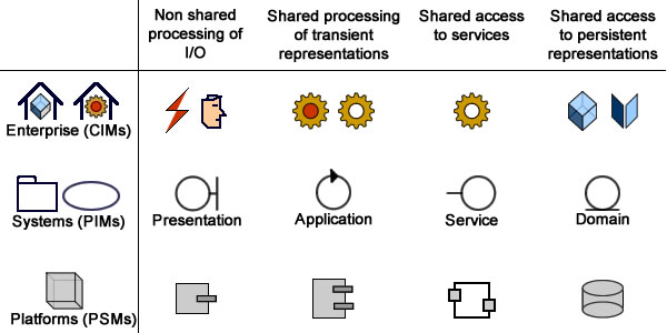


